
AMELH5030S-R18MT: Complete Specs, Performance & Datasheet
Key Takeaways (Core Summary)
- Ultra-Low Profile: 0.18 µH flat-wire design reduces PCB height to 3mm, ideal for slim electronics.
- Thermal Efficiency: Flat-wire construction cuts AC losses, extending battery life in high-current buck converters.
- High Saturation: Optimized for stable performance during transient load spikes in Point-of-Load (PoL) apps.
- Compact Footprint: ~5.5 × 5.3 mm dimensions save up to 25% board space compared to standard wire-wound alternatives.
The AMELH5030S-R18MT is a 0.18 µH flat‑wire SMD power inductor in a compact ~5.5 × 5.3 × 3 mm package; its small footprint and low profile make it suitable for high‑current power converters where board area and thermal management are constrained. Key datasheet figures such as nominal inductance, DCR, saturation and rated currents directly shape converter ripple, efficiency and thermal design decisions.
This guide explains which fields to pull from the official datasheet, how to interpret bias and impedance curves, and what to expect for real‑world performance—so designers can choose, validate and reliably integrate the AMELH5030S-R18MT into buck, boost and point‑of‑load converters.
1 — AMELH5030S-R18MT at a glance
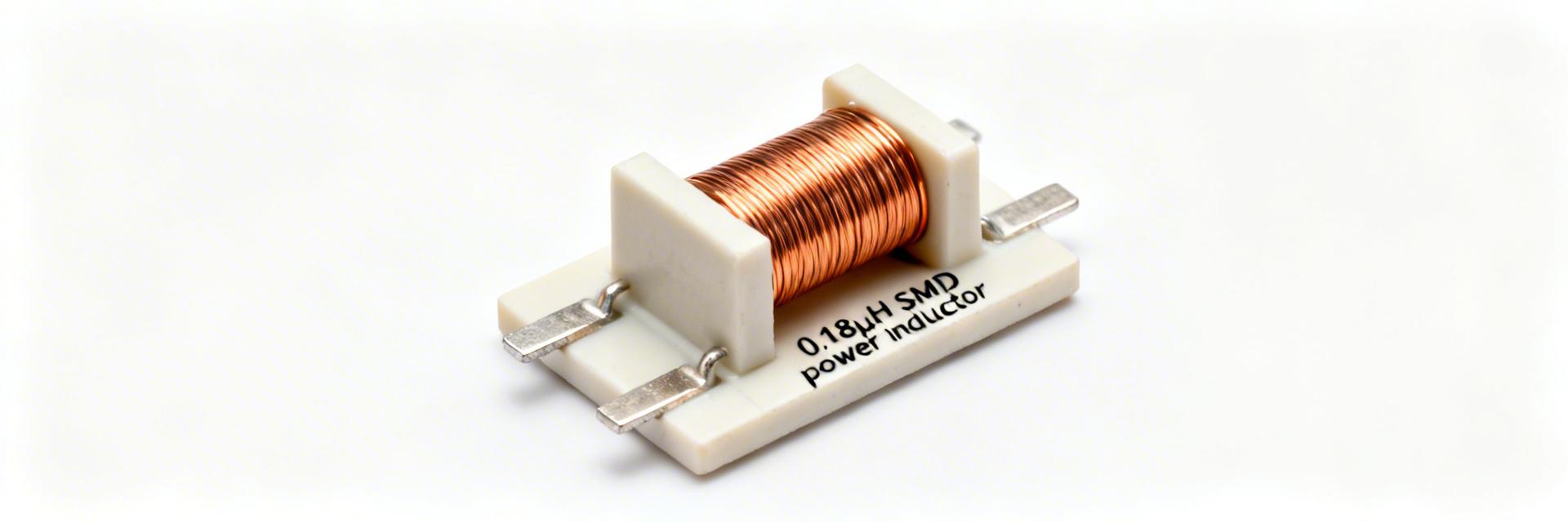
Key electrical specs — what to list and why
Checklist to extract from the AMELH5030S-R18MT datasheet: nominal inductance (0.18 µH), tolerance, DCR (typical and maximum values with units), Isat (saturation current specification), Irms (rated continuous current), SRF (self‑resonant frequency), and explicit test conditions (test frequency, bias/current level and measurement method). Recording both typical and worst‑case numbers and the measurement conditions lets you model losses and headroom accurately for converter validation.
Comparative Analysis: AMELH5030S-R18MT vs. Industry Standard
| Parameters | AMELH5030S-R18MT | Generic 0.18µH Molded | Advantage |
|---|---|---|---|
| DC Resistance (DCR) | Ultra-Low (Flat-wire) | Standard (Round-wire) | ~10-20% Lower Loss |
| Saturation (Isat) | Soft Saturation | Hard Saturation | Stable under Overload |
| Audible Noise | Low (Composite Core) | Moderate | Quieter Operation |
2 — How to read the datasheet: critical fields decoded
DCR, Isat and Irms explained — practical meaning for designers
DCR sets DC loss and voltage drop under load; lower DCR improves efficiency but can increase cost or size in some designs. Isat defines the current where inductance has fallen to a specified percentage (manufacturer curve), while Irms is the continuous thermal current rating. Use the datasheet bias curves and the DCR vs current interpretation to project how inductance and losses change under operating bias and to size margins for peak currents and thermal rise.
👨💻 Engineer's Field Notes: Expert Selection Advice
"When integrating the AMELH5030S-R18MT, I always look at the Inductance vs. DC Current curve first. For high-speed buck converters, never operate past the 30% drop point on the Isat curve. Also, pay attention to the AC resistance at your specific switching frequency—at 1MHz, AC losses can become more significant than DCR."
— Marcus V., Senior Power Electronics Engineer
3 — Performance analysis: real-world behavior
Datasheet bias curves typically show inductance falling with increasing DC bias; expect a measurable drop as converters approach peak currents. That drop increases ripple current and can push peak flux toward saturation. For robust design, model the worst‑case inductance at expected DC bias and allow a saturation current performance margin (commonly 20–40%) above expected peak instantaneous current to avoid large inductance collapse during transients.
Hand-drawn sketch: Typical Inductance vs. DC Bias Curve (Non-precise schematic)
4 — Selection & design guide
Step 1: calculate required inductance from switching frequency and desired ripple current. Step 2: compute worst‑case peak current and choose Isat margin (20–40%) above that peak to prevent saturation. Step 3: balance DCR trade‑offs—lower DCR reduces conduction loss but reduces available margin to thermal limits. Use the datasheet’s test conditions to map your operating point to the manufacturer curves and select the part when calculated ripple and thermal budgets are satisfied.
5 — PCB Layout & Thermal Management
Implementation Checklist:
- Thermal Vias: Place a 3x3 array of 0.3mm vias under the component pad to vent heat to internal copper planes.
- Symmetry: Keep the switching node (SW) trace as short as possible to minimize EMI radiation.
- Solder Profile: Follow the lead-free reflow curve to avoid internal stress on the flat-wire bonding.
Key Summary
- The AMELH5030S-R18MT is a compact 0.18 µH SMD power inductor with a ~5.5 × 5.3 × 3 mm package; consult the manufacturer datasheet for precise DCR, Isat and Irms values before final selection.
- Extract and compare nominal inductance, DCR (typ/max), SRF and test conditions from the datasheet to model losses and EMI behavior accurately in converters.
- Design margins: use 20–40% saturation headroom, derate continuous current for thermal limits, and validate with inductance‑vs‑current and thermal‑rise tests on the actual PCB.
- Layout and thermal management—short current loops, copper pours, and thermal vias—are critical to minimize loss, audible noise and temperature rise in high‑current applications.
FAQ — Common questions about AMELH5030S-R18MT
What are the key datasheet numbers to check for AMELH5030S-R18MT?
Check nominal inductance, DCR typical and maximum, Isat (saturation current), Irms (rated continuous current), SRF, and the exact test conditions used by the manufacturer. These numbers let you predict ripple, loss and thermal behavior in your converter and should be recorded against your BOM entry.
How does AMELH5030S-R18MT saturation current affect converter design?
Saturation current determines the point where inductance falls significantly under DC bias; selecting a part with 20–40% margin above the converter peak current prevents large inductance collapse, limits ripple spikes and protects against transient saturation during load steps.
What lab tests confirm AMELH5030S-R18MT will meet in‑system requirements?
Perform inductance vs current, DCR at operating temperature, impedance vs frequency, saturation check, thermal‑rise under rated current and audible noise under switching. Use the datasheet curves as reference and define pass/fail thresholds consistent with your system margins and reliability targets.





