
Measured performance highlights—SRF in the tens of MHz, DC resistance in the milliohm range, and rated saturation currents above several amps—make this family a common choice for high-current SMD power applications. This article condenses the HCM1A1307V3 datasheet into a practical reference for design and validation.
Product Overview & Key Specs
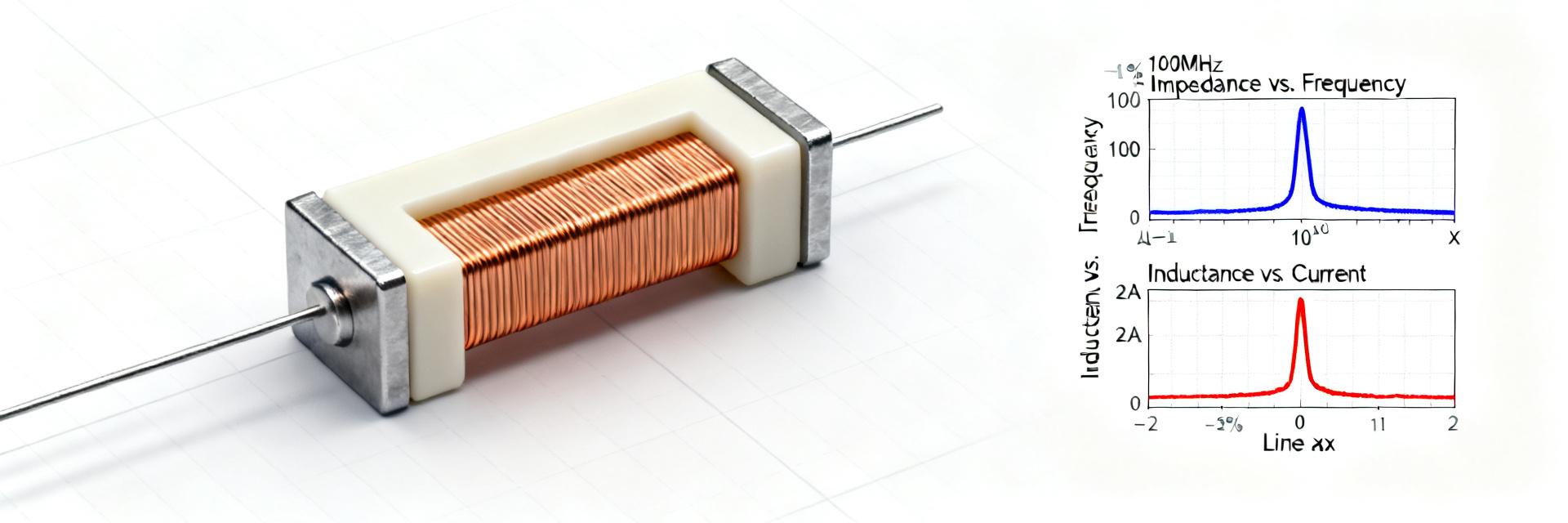
| Parameter | Typical / Range | Notes (Test Conditions) |
|---|---|---|
| Inductance (L) | 0.33 µH – 56 µH | Measured at 100 kHz, 0.25 Vrms, 0 A, +25 °C |
| Tolerance | ±20% | Standard Automotive Class |
| Rated Current (Irms) | Up to 50A+ | Based on ΔT Rise Spec |
| Saturation Current (Isat) | Model Dependent | Specified as L drop to 30% of nominal |
| DC Resistance (DCR) | 0.5 mΩ to 50 mΩ | Measured at +25 °C |
| Operating Temp | -40 °C to +125 °C | Includes self-heating effects |
Detailed Electrical Characteristics & Limits
DC Behavior & Losses
DCR defines I²R losses and temperature rise. At 10 A, a part with 10 mΩ DCR generates 1W of heat. Designers must account for the temperature coefficient of copper, as resistance will increase by approximately 0.39% per °C rise, potentially degrading efficiency at peak thermal loads.
Frequency Response & SRF
The Self-Resonant Frequency (SRF) signals where parasitic capacitance overrides inductance. For stable converter operation, the switching frequency should be kept significantly below the SRF to avoid unexpected impedance peaks and EMI issues.
Application Guidance & PCB Integration
| Condition | Recommended Derating |
|---|---|
| Free air, optimal copper pour | 0–10% |
| Constrained airflow / High density | 10–20% |
| Enclosed unit, High ambient | 20–30% |
Summary
- High-Current Suitability: Combines low DCR and high Isat for efficient power stages.
- Measurement Priorities: Always capture L vs I and DCR vs T for stability tuning.
- PCB Layout: Minimize loop area and maximize copper for heat spreading to ensure long-term reliability.
Frequently Asked Questions
What nominal inductance values are available for HCM1A1307V3 parts?
Typical nominal inductances span sub-microhenry to tens of microhenry variants. Lower L values (e.g., 0.33 µH) are optimized for high-frequency switching, while higher values (e.g., 56 µH) reduce output ripple.
How does DC bias affect HCM1A1307V3 inductance in practice?
As DC current increases, the core begins to saturate, leading to a drop in effective inductance. It is critical to select a part where the saturation current (Isat) exceeds the peak inductor current under worst-case transients.
What test steps should be used to validate HCM1A1307V3 performance?
Validation should include LCR meter verification at 100kHz, in-circuit thermal imaging at maximum load, and transient load response testing to ensure no core saturation occurs during step changes.
What is the recommended derating for high-temperature environments?
In environments with limited airflow or high ambient temperatures (>85°C), we recommend derating the continuous Irms by 20-30% to prevent the component from exceeding its +125°C thermal limit.





