
The HPAL1V0624-R68-R delivers a nominal inductance of 680 nH (0.68 µH) and a rated current near 16.0 A, making it suited to high-current buck converters and power rails. This article is a focused walkthrough of the HPAL1V0624-R68-R datasheet, explaining which electrical and thermal numbers matter in practice and how to validate them in a design.
1 — Product overview & datasheet at a glance
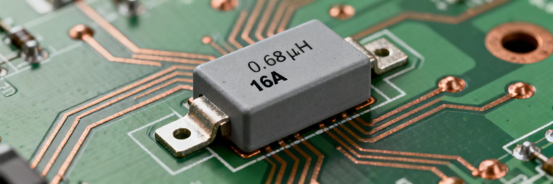
Capturing headline numbers forms a quick pass/fail assessment. The HPAL1V0624-R68-R datasheet lists nominal inductance at 680 nH and rated current at ~16.0 A. Secondary parameters like DCR, Isat, and SRF must be extracted to determine the usable frequency range and saturation margin.
Key electrical parameters
| Parameter | Value / Note |
|---|---|
| Nominal Inductance | 680 nH (0.68 µH) |
| Rated Current (Irated) | ~16.0 A |
| DCR (typ/max) | Single-digit mΩ range (See OEM sheet) |
| Saturation Current (Isat) | Used for peak/ripple headroom |
| SRF | Limits usable switching frequency |
| Operating Temp | Observe derating at elevated T |
Mechanical & mounting details
Mechanical constraints drive layout success. The HPAL1V0624-R68-R is an SMD two-pad package. Engineers should reproduce the recommended land pattern and pad fillet clearances in the PCB CAD to avoid tombstoning and thermal bottlenecks.
2 — Electrical performance & frequency response
DCR and impedance vs frequency directly affect converter efficiency and EMI. Datasheet DCR gives copper loss, while impedance plots show the transition to the Self-Resonant Frequency (SRF). Use both to predict ripple attenuation and resonance risks.
DC resistance (DCR) and efficiency
Quantify copper loss (Pcu = I_rms² × DCR) to size the thermal budget. For example, at 12 A DC with 5 mΩ DCR, Pcu ≈ 0.72 W. Include this in the converter heat balance to ensure the board temperature rise remains within limits.
3 — Thermal behavior & current handling
Rated current (Irms) and saturation current (Isat) define the safe operating area. Isat is the point where inductance drops (typically 20-30%). Plan for peak ripple current to stay below this threshold while applying derating curves for high-temperature environments.
PCB layout and cooling
Layout directly affects current handling. Large pads, via stitching, and wide copper pours reduce temperature rise. Follow recommended pad geometry and provide airflow or a copper heatsink plane where possible to maximize the part's performance.
4 — Selection & Validation Checklist
A methodical checklist prevents surprises during validation. Confirm L tolerance, compare Irated/Isat to peak currents, and budget losses from DCR. Document margins (typically 20–50%) for saturation and thermal headroom when finalizing the BOM.
Summary
- Headline specs: 680 nH and ~16.0 A guide initial suitability; confirm DCR and SRF from the datasheet.
- Thermal management: Use Pcu = I_rms²·DCR to estimate heating; validate with thermal imaging.
- Layout: Wide pads and via stitching are mandatory for high-current stability and derating compliance.
Frequently Asked Questions
What key numbers should I check first in the HPAL1V0624-R68-R datasheet?
Check nominal inductance (680 nH), rated current (~16.0 A), DCR, saturation current (Isat), and self-resonant frequency (SRF). These govern ripple, loss, and frequency limits.
How do I use inductor specs to estimate losses in my converter?
Use the DCR to calculate copper loss using P = I_rms² × DCR. Ensure you include both the DC current and the RMS component of the ripple current.
What bench tests confirm the HPAL1V0624-R68-R will meet my needs?
Key tests include LCR measurement at frequency, impedance sweeps for SRF, DC current ramps for saturation checks, and thermal imaging under steady-state load.
Why is PCB layout critical for the HPAL1V0624-R68-R?
Layout affects current handling and thermal dissipation. Proper pad geometry, via stitching, and wide copper pours are necessary to prevent overheating and maintain stable inductance.





