
The MPIA2512V3-1R0-R is a high-performance 1.0 µH shielded, molded power inductor engineered for modern power electronics. Featuring a 4.1 A continuous current rating (Irms) and a 4.4 A saturation threshold (Isat), this component targets point-of-load (PoL) regulators and compact DC–DC converters where thermal efficiency and board space are at a premium. With a maximum DC resistance (DCR) of approximately 44 mΩ, it balances low conduction losses with a robust 2512 surface-mount footprint.
Background & Product Context
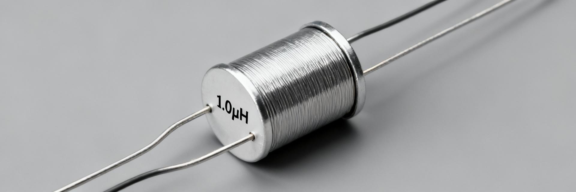
The MPIA25 V3 series represents a refined generation of inductors optimized for automotive and industrial grade environments. The "V3" designation indicates material improvements that enhance current handling and mechanical integrity compared to earlier iterations. Its 2.5 mm × 1.2 mm class footprint makes it a staple for high-density power modules.
Series Identity & Material Notes
Constructed as a shielded molded inductor with a ferrite core, the device utilizes silver or nickel barrier plating over copper terminations. This construction ensures lower radiated EMI and superior resistance to vibration. The molded design provides mechanical protection and thermal stability, crucial for automotive subsystem rails and industrial control units.
Deep Electrical Specifications & Interpretation
Understanding the nominal inductance under specific test conditions is vital for converter stability. The following table highlights the critical parameters extracted from the laboratory specifications.
| Parameter | Typical Value / Condition |
|---|---|
| Nominal Inductance (L) | 1.0 µH |
| Tolerance | ±20% |
| DC Resistance (DCR Max) | 44 mΩ |
| Rated Current (Irms) | ~4.1 A (ΔT = 40°C) |
| Saturation Current (Isat) | ~4.4 A (ΔL/L = 30%) |
| Test Frequency | 100 kHz - 1 MHz |
Frequency Response & Thermal Guidance
The Self-Resonant Frequency (SRF) defines the upper limit of inductive behavior. For the MPIA2512V3-1R0-R, SRF typically resides well above the common 100 kHz to 2 MHz switching range. Operating near SRF can lead to capacitive behavior and EMI issues. Designers should ensure switching harmonics do not coincide with impedance peaks.
Thermal Derating & Reliability
Rated for operation between −40 °C and +125 °C, the part requires careful thermal management. At 85 °C ambient, the allowable Irms may drop to approximately 3.3 A. Efficient heat sinking through PCB copper pours is essential to maintain the part's lifecycle and prevent core saturation due to temperature-induced permeability shifts.
Design & Application Guidance
- Selection Rule: Maintain total peak current (DC + Ripple) below 80% of Isat (approx 3.5 A) for maximum stability.
- Efficiency: Calculate I²R losses: (4.1 A)² × 0.044 Ω ≈ 0.74 W at full load.
- Layout: Use wide traces and place input capacitors immediately adjacent to the inductor to minimize the switch-node loop area.
Procurement Checklist
| Checklist Item | Target Requirement |
|---|---|
| Packaging | Tape & Reel (Standard SMT) |
| Compliance | RoHS, AEC-Q200 (Confirm Grade) |
| Lifecycle | Active / Long-term availability |
| Samples | Lot-level DCR & L verification |
Summary
The MPIA2512V3-1R0-R offers a balanced solution for 4A-class power rails, combining a compact footprint with robust saturation characteristics. Engineers should prioritize DCR modeling and thermal derating to ensure long-term reliability in high-density automotive and industrial designs.
FAQ
What are the critical datasheet figures to check for the MPIA2512V3-1R0-R?
Key figures are nominal inductance, tolerance, DCR (typ/max), Irms, Isat and the impedance/SRF plot. Also review thermal derating curves and solder/reflow profiles. These parameters determine efficiency, thermal behavior and suitability in your converter’s switching frequency band.
How should I size margin between Irms and Isat for reliable operation?
Maintain DC plus peak ripple currents below ~70–80% of Isat to avoid significant inductance collapse during transients. For continuous operation, keep steady current below ~70–80% of Irms after accounting for PCB thermal resistance and ambient. Adjust margins based on measured temperature rise and application criticality.
What procurement checks reduce risk for production using this power inductor?
Request tape-and-reel samples, lot traceability, solderability reports and sample test data for L vs current and DCR vs temperature. Run assembly-level thermal and vibration tests, and validate performance on your real PCB to ensure the part meets efficiency and reliability targets before full production purchasing.
Why is the shielded molded design important for 2512 inductors?
The molded shield reduces radiated EMI and improves mechanical robustness against vibration, making it ideal for compact automotive and industrial environments where signal integrity is paramount.





