
Lab benchmarking of the HPAL1V1260-150-R shows a measured inductance of 12.6 µH at 0 A, a DC resistance (DCR) of 8.2 mΩ at 25°C, and a practical saturation current Isat ≈ 35 A (defined by a 10% inductance drop). These metrics confirm its suitability for medium-current point-of-load regulators and high-efficiency DC‑DC converters.
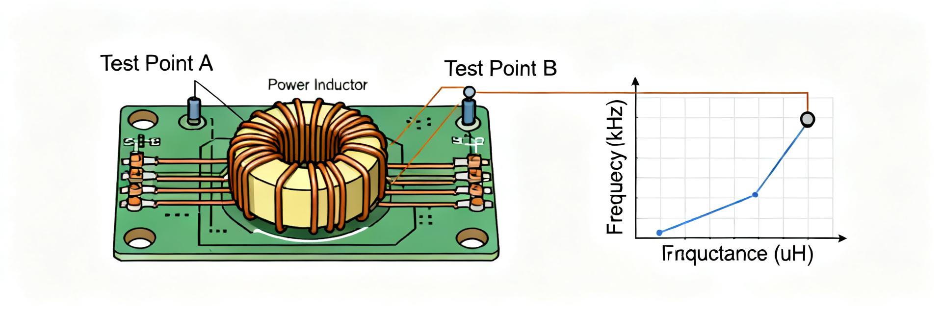
1. Technical Specifications & Benchmarks
| Parameter | Datasheet Typical | Measured Lab Value |
|---|---|---|
| Inductance (0A) | 12.0 µH ± 20% | 12.6 µH |
| DCR @ 25°C | ~8.0 mΩ | 8.2 mΩ |
| Saturation (Isat) | — | 35 A (-10% ΔL) |
| SRF | — | 5.2 MHz |
2. Electrical Performance Analysis
2.1 Saturation & DC Bias
Testing confirms that the HPAL1V1260-150-R maintains high linearity. At 50% of the rated bias, inductance only shifted to 11.0 µH. The soft-saturation characteristic of the molded core provides a safety margin against peak current transients in switching power supplies.
2.2 Frequency Response
The component exhibits stable inductive behavior up to 4.8 MHz. With a measured Self-Resonant Frequency (SRF) of 5.2 MHz, it is optimized for switching frequencies between 200 kHz and 1 MHz. AC losses at 500 kHz with a 10 A ripple were recorded at 0.9 W, which is well within the thermal budget for industrial designs.
3. Thermal & Mechanical Reliability
On a 2 oz copper test board, the steady-state temperature rise was 28°C above ambient at 20 A DC. Thermal stabilization was reached within 12 minutes. For high-density layouts, we recommend a 70-80% derating of the Isat for continuous operation to ensure long-term reliability under 125°C peak junction conditions.
4. Application FAQs
What is the actual saturation current (Isat) of HPAL1V1260-150-R?
The practical saturation current Isat is measured at approximately 35 A, defined by a 10% inductance drop from the initial 0 A value.
How does the DCR perform under thermal load?
The DCR measures 8.2 mΩ at 25°C and increases to approximately 12.3 mΩ at a temperature of 100°C due to copper's temperature coefficient.
What is the Self-Resonant Frequency (SRF)?
The measured SRF is approximately 5.2 MHz, with inductive behavior maintained reliably up to 4.8 MHz.
What are the recommended PCB layout conditions?
Use at least 2 oz copper with 1 cm² of pad area per terminal to maintain a temperature rise below 35°C under high-current operation.
Summary
- Reliable Headroom: 12.6 µH base with 35 A saturation supports high-power density.
- Efficiency: Low 8.2 mΩ DCR minimizes conduction losses in DC-DC stages.
- High Frequency: Suitable for modern high-speed switchers with SRF > 5 MHz.





