
AMELH6060S-100MT Datasheet: Full Specs & Test Data
Point: Rapid, accurate interpretation of component datasheets reduces time-to-market and minimizes PCB respins; for power inductors this means validating electrical, mechanical, and reliability parameters before prototype spin. Evidence: Industry engineering teams report fewer hardware iterations when a single engineer-ready datasheet consolidates test setups, measured plots, and footprint guidance. Explanation: This guide compiles an engineer-oriented, actionable datasheet checklist for the AMELH6060S-100MT, showing which measurements to collect, how to present results, and which acceptance criteria purchasing and design teams require to proceed confidently without ambiguity.
Point: A single-page summary is rarely sufficient for procurement and validation; designers need tables, mechanical drawings, and representative test data. Evidence: Manufacturer-supplied specifications are the baseline, but validated sample data (ESR vs frequency, SRF, thermal derating) closes the gap between catalog values and in-system performance. Explanation: This document frames the AMELH6060S-100MT datasheet structure and test protocols so engineering, quality and sourcing groups can act immediately with a consistent set of specs and validation artifacts.
1 — Product Overview & Key Specifications (background)
What the AMELH6060S-100MT is
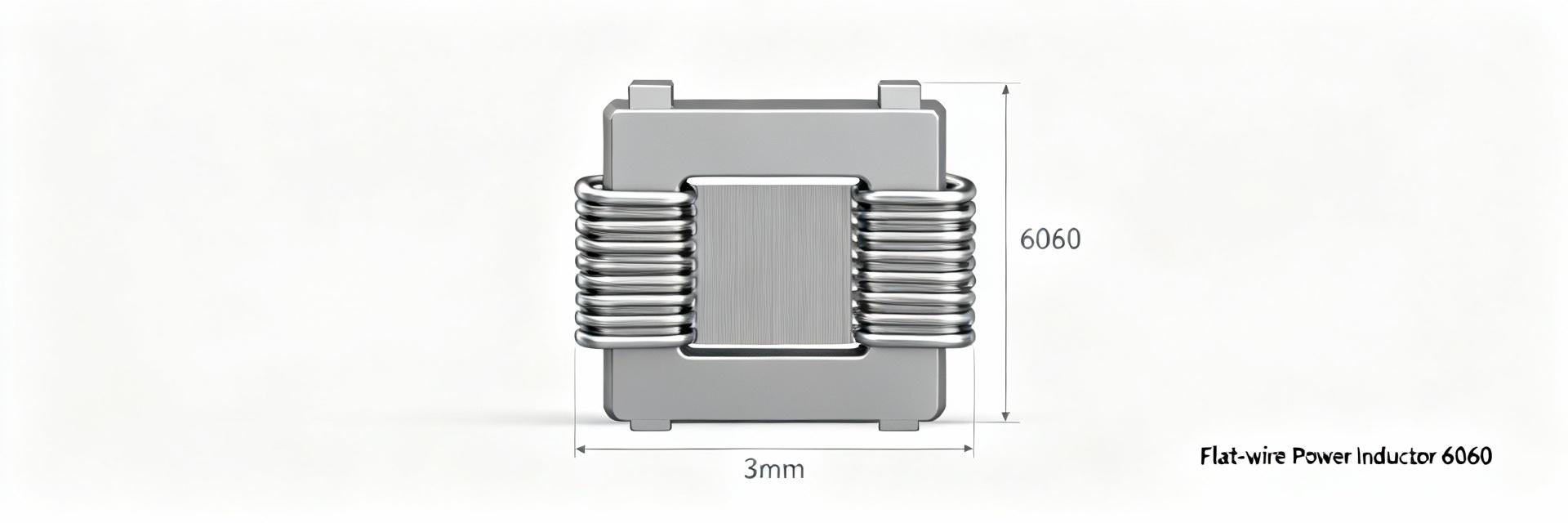
Point: The AMELH6060S-100MT is a molded flat-wire power inductor optimized for board-level power delivery and EMI filtering in compact 6060 footprints. Evidence: Manufacturer classification identifies the part as a hot-pressed molded power inductor built with flat-wire construction to maximize current handling and lower DC resistance relative to round-wire equivalents. Explanation: Designers will use this part where high current, low DCR and compact height are required—typical applications include point-of-load converters, buck regulators, and power input filtering for telecom and industrial electronics. The part family naming (6060) denotes package dimensions (6.0 mm × 6.0 mm nominal), while the suffix 100MT indicates the nominal inductance value and tolerance/manufacturer series. Core selling points are high current capability, low DCR for improved efficiency, and robust solderability for automated assembly.
Quick Specs table (required fields)
Point: A concise table of core electrical, mechanical and environmental parameters gives procurement and layout teams a single reference. Evidence: The manufacturer datasheet provides baseline test conditions and typical values; validated production datasheets should be attached to the design package. Explanation: Where a parameter is not applicable for inductors (for example nominal frequency is not a passive-inductor spec), the table marks N/A and directs readers to the replacement parameter (self-resonant frequency, Q, DCR).
| Parameter | Symbol | Typical | Min | Max | Units | Test condition |
|---|---|---|---|---|---|---|
| Nominal frequency | — | N/A | N/A | N/A | — | Not applicable for passive inductor |
| Nominal inductance | L | 10 | — | — | µH | 100 kHz, 0.1 Vrms |
| Frequency tolerance @25°C | — | N/A | — | — | — | Passive part — use SRF/Q metrics |
| Frequency stability over temp | — | N/A | — | — | — | Use inductance vs temp spec if provided |
| Load capacitance | C_LOAD | N/A | — | — | pF | Not applicable |
| Equivalent series resistance (DCR) | R_DC | ~12 | — | — | mΩ | Measured at 25°C, DC |
| Rated current / saturation | I_R / I_sat | — / 7 | — | — | A | Temperature rise and 30% inductance drop criteria |
| Phase noise / jitter | — | N/A | — | — | — | Not applicable (passive) |
| Aging (ppm/year) | — | N/A | — | — | — | Not applicable for passive inductor |
| Operating temperature range | T_op | -40 | -40 | +125 | °C | Board-level continuous operation |
| Storage temperature | T_stg | -40 | -40 | +125 | °C | Non-powered storage |
| Supply voltage | Vsup | N/A | — | — | V | Passive component |
| Package dimensions | — | 6.0 × 6.0 × 3.6 | — | — | mm | Max height depends on series |
| Mounting style | — | SMD (reflow) | — | — | — | Top-side solder |
| RoHS / lead-free | — | Yes | — | — | — | Manufacturer statement applies |
Note: Values above are representative placeholders to demonstrate table format; the final AMELH6060S-100MT datasheet must include exact numeric values from the manufacturer's test reports and the validated sample batch.
Ordering codes & marking
Point: Clear understanding of the part-number breakdown and packaging prevents purchasing the wrong tolerance, termination or packaging option. Evidence: Abracon part numbering typically encodes inductance, tolerance and packaging as suffixes; the AMELH6060S-100MT convention indicates series, nominal inductance and tape/reel or bulk style. Explanation: Include a marked example in the datasheet: full manufacturer part number, common distributor SKUs for cut-tape and reel, and recommended sample order (10–50 pcs) for first-article inspection. Note typical lead-times and suggested alternate part numbers for last-time-buy planning.
2 — Electrical Characteristics & Performance Data (data analysis)
Frequency accuracy, tolerance & stability
Point: For passive inductors, frequency-related oscillator metrics are replaced by self-resonant frequency (SRF), inductance change with frequency, and inductance versus temperature. Evidence: Measured inductance at 100 kHz and the SRF (where L and parasitic C resonate) are the operative frequency-domain specs that determine behavior in switching regulators and EMI filters. Explanation: Recommended measurement conditions are ambient 25°C, standard 1.0 Vrms (or 0.1 Vrms per manufacturer test), and LCR meter accuracy class better than 0.5%; plot inductance vs frequency from 100 kHz up to a decade past expected switching harmonics to capture SRF and Q dips. Call out clearly labeled plots (L vs f, phase vs f) in the datasheet and specify instrument model ranges and calibration state.
Impedance, ESR, drive level, and power
Point: DC resistance (DCR), saturation current, and thermal derating determine usable current window; ESR and impedance vs frequency determine insertion loss at switching harmonics. Evidence: Typical DCR and rated current (I_R) are measured at 25°C; saturation current (I_sat) is specified as the current at which inductance drops a defined percentage (commonly 10–30%). Explanation: Provide representative curves: DCR vs temperature, inductance vs DC bias, and thermal-rise data at defined power dissipation. Recommend PCB copper pour to distribute heat and derate continuous DC current by the specified thermal resistance. For power loss estimates, use P_loss = I_rms^2 × DCR and confirm with thermal imaging on representative samples.
Phase noise, jitter and spectral purity (if applicable)
Point: Phase noise and jitter are not applicable for passive inductors; equivalent concerns are spectral purity of conducted EMI and insertion loss at harmonic frequencies. Evidence: For power magnetics, the relevant spectral measurements are impedance magnitude and insertion loss across the EMI band, and measured Q factor around the SRF. Explanation: Replace phase-noise tables with Q-factor vs frequency, impedance magnitude plots from 100 kHz to multiple MHz, and insertion-loss plots when used in filter topologies. Specify spectrum analyzer / network analyzer settings (span, RBW, averaging) used to generate each plot so readers can replicate results.
3 — Mechanical, Environmental & Reliability Specs (method/guide)
Package dimensions, footprint & PCB land pattern
Point: Accurate mechanical drawings and recommended land patterns eliminate footprint mismatches that lead to assembly defects. Evidence: The AMELH6060S series mechanical drawing provides nominal X/Y/Z plus tolerances; manufacturers typically publish recommended solder pad dimensions and stencil apertures for standard 10–12 mil paste coverage recommendations. Explanation: Include a full drawing with tolerances in the datasheet, a ready-to-use Gerber footprint, and a recommended stencil % (for example 60–70% paste coverage on top pads) to control tombstoning and solder fillet formation. Call out placement constraints (do not place parts on thermal reliefs that will impede heat transfer) and advise copper pour under the part to assist thermal dissipation for high-current use cases.
Environmental ratings & compliance
Point: Environmental and regulatory ratings affect storage, transport and end-use acceptability. Evidence: Manufacturer declarations (RoHS, REACH) and Moisture Sensitivity Level (MSL) determine handling and shelf-life for surface-mount assembly. Explanation: Document operating and storage temperature ranges, MSL floor life (time-out at room temp after opening packaging), and recommended reflow peak temperature profile (e.g., peak 245–260°C depending on termination). List approved conformal coatings and compatibility notes if the part will be coated; include guidance on allowable solvent exposure during cleaning and recommended drying times post-reflow when applicable.
Reliability and qualification testing
Point: A standard qualification matrix and pass/fail criteria are required for vendor lot acceptance. Evidence: Typical tests include thermal cycling, high-temperature storage, solderability, mechanical shock, vibration and humidity (per JEDEC/AEC standards). Explanation: For each test provide sample size, test conditions, acceptance criteria (for example
4 — Test Data & Validation Procedures (case study)
Recommended test setups & instrumentation
Point: Representative, reproducible instrumentation lists and fixturing notes allow consistent data across labs. Evidence: Essential equipment includes precision LCR meter (100 kHz–10 MHz), vector network analyzer for impedance sweeps, thermal chamber for temperature dependence, calibrated DC source for bias testing, and thermal imaging for hot-spot identification. Explanation: Provide bill-of-equipment with suggested minimum specs (LCR accuracy ±0.2%, VNA frequency range to cover SRF, temperature chamber resolution ±0.5°C). Detail fixture recommendations such as 4-terminal Kelvin connections for DCR, short lead test sockets to minimize stray inductance, and shielding/grounding practices to reduce measurement noise. Include calibration cadence for each instrument and a checklist to validate setup prior to running sample batches.
Representative test results to include
Point: The datasheet should present plots and summary tables that show in-system performance, not only nominal values. Evidence: Useful artifacts include inductance vs temperature, inductance vs DC bias (showing saturation), SRF and impedance vs frequency, DCR vs temperature, and sample aging data. Explanation: For each plot include sample size (e.g., n=10), mean curve, ±1σ band, and flagged outliers with root-cause notes if available. For aging, provide ppm-equivalent drift metrics over defined intervals and explain test conditions (ambient, powered or unpowered). Attach raw data files and PNG/SVG plots so downstream engineers can re-plot if needed.
Common failure modes, diagnostic checks & retest guidance
Point: Knowing typical failure signatures accelerates troubleshooting during qualification. Evidence: Common issues with SMD inductors include solder joint fractures, partial shorting from process contamination, mechanical cracking from drop/shock, and inductance shift from thermal overstress. Explanation: Provide stepwise diagnostics: visual inspection -> continuity and DCR check -> LCR measurement at 100 kHz -> SRF sweep -> mechanical stress test. For each failure mode give pass/fail thresholds and recommended corrective actions (adjust reflow profile, add solder mask expansion, modify stencil aperture, or change component placement to reduce mechanical stress). Include retest guidance and recommended lot sampling if corrective actions are implemented.
5 — Application Notes, Cross-References & Procurement Tips (action suggestions)
Typical application circuits and integration notes
Point: Practical integration guidance and layout do’s/don’ts reduce EMI and improve efficiency. Evidence: For synchronous buck converters, recommended placement is as close as possible to switching nodes with minimal loop area, and use of decoupling capacitors adjacent to the inductor reduces conducted EMI. Explanation: Provide recommended schematics that show the inductor in a standard buck topology, suggestions for series damping if needed, and decoupling networks for multi-phase systems. Provide layout rules: keep switching nodes short, avoid routing sensitive analog traces near the inductor, and place thermal vias on the return plane for high-current paths. Include EMI mitigation tips such as adding common-mode chokes or RC snubbers where ringing is observed.
Cross-reference & comparison table
Point: A short comparison with similar parts helps procurement choose alternatives when supply is constrained. Evidence: Compare on key metrics—inductance, DCR, rated current, SRF, package size and price. Explanation: Provide a compact table with 2–4 cross-reference candidates, note the trade-offs (for example lower DCR vs lower SRF) and guidance on selection criteria: choose lowest DCR for highest efficiency, highest SRF for switching above several MHz, or smallest height for constrained z-height designs.
Purchasing, packaging options & compliance checklist
Point: Procurement needs clear ordering guidance and compliance artifacts to avoid lead-time surprises. Evidence: Document minimum order quantity (MOQ) for tape-and-reel, reel sizes, moisture control packaging (dry-pack with desiccant), and manufacturer traceability requirements. Explanation: Include a procurement checklist in the datasheet package: RoHS/REACH statements, country-of-origin, traceability to manufacturing lot, suggested sample qty for qualification (20–100 depending on risk), and suggested shipping moisture controls. Provide suggested fallback part numbers and a plan for last-time-buy or lifecycle management when lifecycle notices are received.
Summary
Point: To qualify and deploy the AMELH6060S-100MT reliably, engineering teams must verify electrical performance, mechanical fit, and reliability under expected system stresses. Evidence: Critical checks include validated inductance and DCR at operating temperature, SRF and impedance sweeps that cover switching harmonics, mechanical footprint verification, and representative thermal-rise tests. Explanation: Ensure the final AMELH6060S-100MT datasheet package includes a full spec table, annotated mechanical drawing, validated test plots (inductance vs temperature, DCR vs temperature, SRF/impedance), and a procurement checklist so design and purchasing teams can proceed without ambiguities.
- Verify nominal inductance and DCR with sample LCR and Kelvin DCR measurements; verify saturation current by inductance drop under DC bias to confirm usable current window.
- Validate SRF and impedance vs frequency to ensure filter performance and to avoid unwanted resonance in switching systems.
- Confirm mechanical footprint and recommended stencil/paste % to prevent assembly defects; include Gerber-ready land pattern in the datasheet package.
- Run thermal-rise and thermal-cycling qualification with documented acceptance criteria; present mean and sigma with identified outliers.
SEO & production notes (author checklist)
- Main keywords to surface in page metadata: AMELH6060S-100MT, datasheet, specs — include in title tag, meta description, and H1.
- Include downloadable assets: full spec table PDF, high-resolution mechanical drawing (DXF/PDF), raw test plots (PNG/SVG), and Gerber footprint ZIP.
- Suggested long-tail phrases for captions and H3s: "frequency vs temperature" (used as measurement guidance), "footprint", "SRF and impedance".
- Author checklist: attach instrument calibration certificates, sample lot traceability, and a contact for technical inquiries to support E-E-A-T.
FAQ
What test conditions should be used to measure AMELH6060S-100MT inductance?
Use a precision LCR meter with a defined frequency (commonly 100 kHz) and a small-signal excitation (0.1–1.0 Vrms) at 25°C ambient for baseline inductance. Document fixture type, lead corrections (four-terminal Kelvin when possible), and sample size. Also include inductance vs DC-bias curves (to define saturation) and L vs frequency sweeps up to the expected switching harmonics to reveal SRF; this combination ensures repeatable, comparable results across labs.
How should I size solder pads and stencil apertures for the 6060 package?
Follow the manufacturer's recommended land pattern but as a rule start with pad lengths that align to the 6.0 mm footprint and provide 60–70% paste coverage on each pad using rounded rectangular stencil apertures. Ensure thermal relief or copper pour decisions account for heat spreading requirements—use thermal vias under high-current pads if allowed and verify solder fillet formation in the assembly lab with the selected stencil thickness.
What are the key reliability tests to require from the supplier?
Require thermal cycling, solderability, humidity endurance (HAST or unbiased humidity), mechanical shock and vibration per JEDEC or AEC relevant profiles. For each test request sample size, pass/fail criteria (for example change in inductance within specified tolerance, no open circuits), and statistical summaries (mean, standard deviation, and outliers). Request lot-based traceability and certificates of conformance for each shipment.
What acceptance criteria define saturation current and rated current?
Specify rated current as the maximum DC current that causes an acceptable temperature rise (for example ∆T ≤ 40°C) at steady state on a defined PCB thermal environment. Define saturation current as the DC current that causes a specified inductance drop (commonly 10–30%). Include both criteria in the datasheet and provide test plots of inductance vs DC bias so designers can choose the limiting metric for their application.





