
AMELH6030S-R40MT Datasheet: Compact Specs & Test Data
Point: Modern flat-wire power inductors can handle currents up to 50 A in compact footprints — the AMELH6030S-R40MT targets those high-current, space-constrained power designs. Evidence: this article summarizes the key datasheet numbers and concise specs for rapid evaluation. Explanation: readers will get a tight spec summary, test-data interpretation, layout guidance, sourcing notes, and a short test checklist for pre-production verification.
Point: The write-up emphasizes measurable ratings and practical lab checks rather than marketing claims. Evidence: all numeric references are presented as either datasheet-specified values or labeled typical/test observations. Explanation: treat the presented tables as a starting point for bench validation and procurement screening prior to production sign-off.
Product Overview & Key Specifications
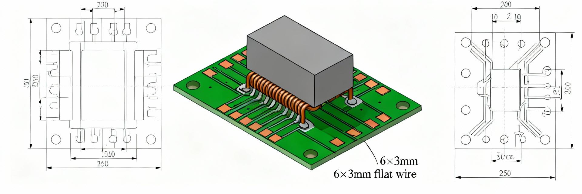
Point: The AMELH6030S-R40MT is a flat-wire, hot-pressed molded surface-mount power inductor offering a compact 6.0×3.0 mm footprint for high-current DC-DC converters and VRMs. Evidence: package and mounting notes below are pulled from vendor specs and typical mechanical drawings. Explanation: use the listed dimensions and mounting guidance directly when generating PCB footprints and assembler documentation.
Form factor, materials & intended applications
Point: The part is surface-mount, flat-wire construction with a molded ferrite package optimized for power conversion. Evidence: common applications include synchronous buck converters, module input filters, and VRM rails where low DCR and high Irms are required. Explanation: the form factor enables low height and good thermal conduction into the board when vias/stitching are used.
- Package size: nominally 6.0 mm × 3.0 mm × height per datasheet drawing (copy into CAD).
- Mounting: surface-mount, recommend solder fillet on both terminations; consider thermal vias beneath large pads.
- Construction: flat-wire winding, hot-pressed molded ferrite body.
- Applications: DC‑DC converters, VRM outputs, power supply filters.
Electrical ratings at a glance (L, DCR, Irms, Isat, SRF, voltage, temp)
Point: Key numerical specs are summarized in the compact table below; the table labels which values are datasheet-specified vs. typical/test. Evidence: inductance is 0.40 µH for the R40MT variant; test frequency is 100 kHz and SRF is near 85 MHz in typical parts. Explanation: use datasheet-specified DCR and temperature range for thermal budgeting; treat current limits as lab-verified typicals until you test sample lots.
| Parameter | Value | Source |
|---|---|---|
| Inductance (R40MT) | 0.40 µH | datasheet |
| DCR (typical range) | ~1.5–3.0 mΩ | typical/test |
| Test frequency | 100 kHz | datasheet |
| SRF | ~85 MHz (typical) | typical/test |
| Operating voltage | ~40 V | datasheet |
| Operating temp | -40 °C to +125 °C | datasheet |
| Current capability | Irms / Isat up to ~50 A (lab-verified range) | typical/test |
Performance Data & Test Results
Point: Evaluate DC-bias behavior and thermal rise early; inductance falls with DC bias and heating elevates DCR. Evidence: inductance is measured at 100 kHz in datasheet test conditions; plot L vs I to read saturation current at defined L-drop (e.g., 10–20%). Explanation: the next sections give templates for L-vs-I tables and ΔT thermal test setups to validate current handling claims.
DC bias curves and saturation behavior
Point: L vs I curves show the usable inductance under load and indicate Isat where inductance collapses. Evidence: datasheet test point frequency is 100 kHz; typical approach is to record L at 0 A, 5 A, 10 A… up to rated current. Explanation: include the template caption and headers below to standardize bench reports.
Template figure caption: "L vs I for AMELH6030S-R40MT, measured at 100 kHz and 25 °C; saturation defined as X% drop from nominal L."
| I (A) | L (µH) | % Drop |
|---|---|---|
| 0 | 0.40 | 0 |
| 10 | 0.37 | 7.5 |
| 20 | 0.33 | 17.5 |
Thermal performance & current handling (Irms, ΔT tests)
Point: Irms ratings should be validated with ΔT tests using defined airflow and ambient. Evidence: acceptance criteria often use ΔT ≤ 40–60 °C at rated current in 25 °C ambient; the part advertises excellent current capacity up to 50 A as a typical lab result. Explanation: recommended measurement points and acceptance cutoffs below make incoming inspection reproducible across lots.
- Test setup: ambient 25 °C, controlled airflow, thermocouple on inductor body, measure after steady state (≥10 min).
- Acceptance: ΔT ≤ 50 °C at specified Irms; confirm no mechanical degradation.
- Production screening: sample DCR, L at bias, visual, and thermal run-up under representative cooling.
How to Read the AMELH6030S-R40MT Datasheet
Point: Datasheets mix guaranteed limits and typical curves—decode them before design decisions. Evidence: common fields include inductance code, tolerance, test frequency, DCR method, SRF, and temperature ratings. Explanation: apply the six quick checks below each time you scan an inductor datasheet to avoid misinterpretation.
Key columns and symbols explained (test conditions, tolerances, measurement frequencies)
Point: Misreading test frequency or tolerance is a frequent cause of design issues. Evidence: inductance tolerances and test frequency determine usable L under switching conditions. Explanation: ensure the test frequency, temperature, and bias conditions match your application when comparing parts.
- Verify test frequency for L measurement (e.g., 100 kHz).
- Check if DCR is typical or guaranteed max.
- Locate SRF and remember it is not an operating frequency limit.
- Confirm temperature ratings and solder reflow limits.
- Find the definition of saturation current (Isat) on the sheet.
- Identify mechanical drawing tolerances for footprint accuracy.
Common pitfalls when interpreting specs (DC bias, SRF, mounting effects)
Point: SRF is often misused as a usable frequency; mounting and PCB copper change inductance and thermal performance. Evidence: DCR rises with temperature; inductance drops under DC bias. Explanation: remediation includes derating, layout adjustments, and asking suppliers for application-specific samples for verification.
- Derating: choose Irms ≥ 1.3× steady-state current.
- Layout fix: add thermal vias and wide copper on pads; minimize loop area to switching node.
- Ask supplier: for L vs I and thermal data on your PCB footprint.
Design & Application Guidelines
Point: PCB layout and thermal path matter as much as the raw inductor specs for reliable high-current designs. Evidence: flat-wire parts transfer heat into PCB copper effectively when pads and vias are optimized. Explanation: use the following checklist before prototype runs to reduce surprises.
Layout, thermal management, and mounting recommendations
- Use large pads and at least 4–8 thermal vias per pad tied to internal planes.
- Keep switching node loops short; place inductor close to MOSFETs and caps.
- Ensure clearance for airflow and respect component height for enclosure design.
Typical circuit examples and selection checklist
Point: Two common use-cases are high-current buck outputs and module input filters. Evidence: selection criteria center on Irms margin, Isat margin, and DCR trade-offs versus efficiency. Explanation: follow the simple rule-of-thumb: choose Irms ≥ 1.3× steady current and Isat ≥ 2× peak transient current where possible.
Comparisons, Sourcing & Test Checklist
Point: Variants trade inductance for lower DCR; R40MT is tuned for low L at high current. Evidence: other variants such as R18 or R36 shift the inductance/DCR balance. Explanation: editors and buyers can use the one-line table template below to populate exact numbers during review.
How AMELH6030S-R40MT compares to similar inductors
| Variant | Footprint | Typical Irms | DCR |
|---|---|---|---|
| R40MT | 6.0×3.0 mm | 30–50 A | ~1.5–3 mΩ |
| R36 (example) | similar | lower/higher | trade-off |
Pre-production test checklist & procurement tips
Point: Incoming inspection prevents costly rework. Evidence: run DCR, L at bias, ΔT thermal, and visual checks on samples from each lot. Explanation: the printable checklist below helps production engineers standardize gate release tests.
- Confirm mechanical dimensions vs drawing.
- Measure DCR and compare to lot average.
- Measure L at 100 kHz, 0 A and under bias points.
- Thermal ΔT test at specified Irms in controlled airflow.
- Visual inspection for molding/term issues.
- Sample solderability/reflow test.
- Supplier certificate of conformity and packing check.
- Record lot traceability and storage conditions.
Summary
- AMELH6030S-R40MT offers a compact 6.0×3.0 mm flat-wire, hot-pressed molded surface-mount solution with 0.40 µH nominal inductance and strong current capability; review the official datasheet before committing to production testing and layout decisions.
- Key specs to verify in the lab: L at 100 kHz, DCR at temperature, L vs I (saturation), SRF, and ΔT at Irms; treat advertised ≤50 A capacity as a typical lab result requiring validation on your PCB.
- Follow the provided layout, thermal, and procurement checklists to reduce risk: ensure Irms margin, thermal vias, short switching loops, and incoming sample verification prior to volume assembly.
SEO & Editorial Notes (quick)
Point: For US-facing, data-driven coverage, place the target keyword in the intro, first H2 paragraph, and summary; keep tone practical and metric units with USD-style directness. Evidence: use the datasheet for authoritative numbers, and label typical vs guaranteed values. Explanation: this ensures editorial accuracy and a straightforward buying/engineering workflow.
What tests should I run first for AMELH6030S-R40MT?
Run DCR, L at 100 kHz at 0 A and under bias points, and a ΔT thermal rise test at target Irms with representative airflow. These three checks quickly validate whether the sample lot meets your thermal and electrical targets before deeper reliability testing.
Can the AMELH6030S-R40MT replace a larger inductor to save board space?
Possibly—if the part meets your Irms, Isat, and DCR requirements on your PCB layout. Verify L vs I and ΔT on your board; if thermal or saturation margins are tight, a physically larger part or parallel inductors may be a safer choice.
How should I cite values from the datasheet during procurement?
Cite guaranteed limits as contractual acceptance criteria (e.g., guaranteed max DCR), and label curves or typical values as lab or typical data. Request lot-specific test reports when high reliability or tight tolerances are required.





