
AMELH6030S-R56MT vs Standard Inductors: DCR, Current & SRF
A compact power inductor promises ultra-low DCR and high continuous current, but how does that translate on the bench compared with a generic standard inductor? This article delivers a focused, engineer-oriented comparison that isolates DCR, rated and saturation current, and SRF to show the trade-offs designers should expect when choosing between a low-profile SMD power inductor and a baseline standard part.
Readers will get a concise spec comparison table, practical measurement checklists, thermal and HF testing steps, and procurement-ready BOM language. The goal is actionable guidance for board-level decisions: minimize conduction loss, avoid SRF surprises at switching harmonics, and verify vendor claims with repeatable tests.
Background: What the AMELH6030S-R56MT part family means vs "standard" inductors
Defining the AMELH6030S-R56MT form-factor & target use-cases
The AMELH6030S-R56MT name denotes a low-profile, high-current SMD power inductor in a compact 6 x 3 mm-ish footprint, optimized for switch-mode power supplies and power modules. Typical construction uses flat or pressed windings and a high-saturation magnetic core to keep DCR low while supporting continuous currents in the 10–30 A band, depending on thermal conditions and PCB cooling.
What "standard inductor" means for this comparison
For baseline comparison a "standard inductor" is a common SMD wire-wound or molded power choke from a lower power tier: larger winding resistance, higher DCR, and lower Isat than modern pressed-winding parts. These reference parts commonly trade size and current capability for lower unit cost; performance varies widely across vendors and price tiers, so define the reference class before spec decisions.
Head-to-head specs comparison: DCR, Rated Current, Isat, and SRF
DCR comparison: datasheet vs practical expectations
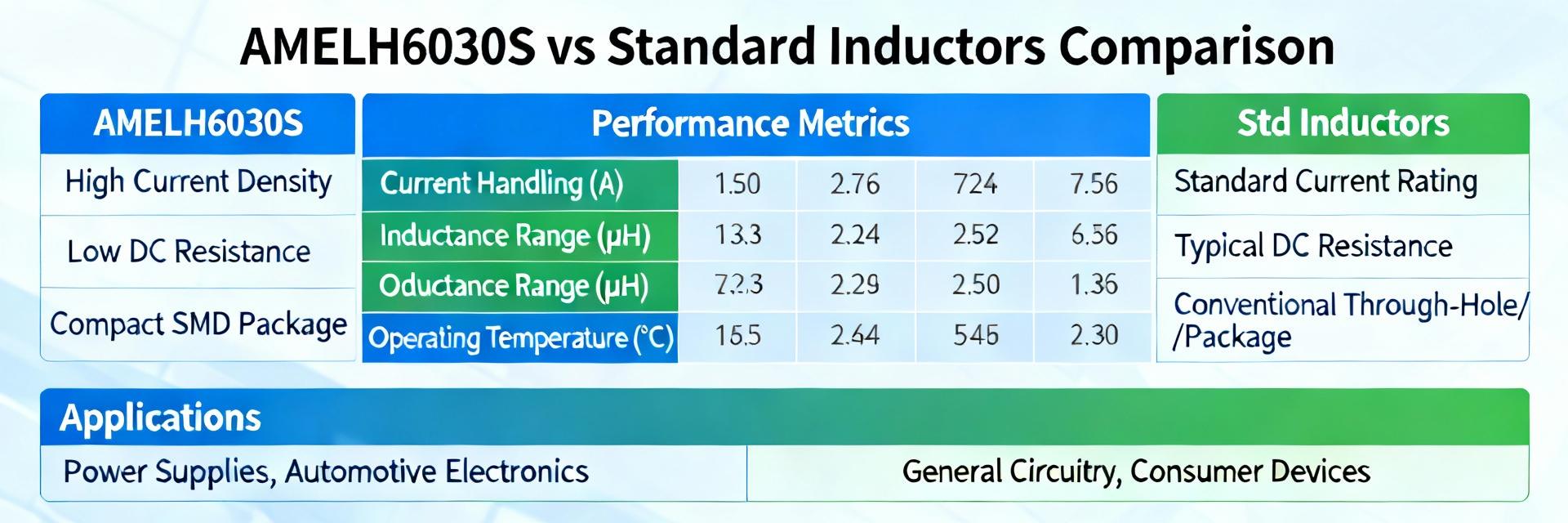
Below is a representative spec table showing nominal values you might see on a datasheet or measured in-lab. Values are illustrative example figures; always record measurement conditions (25°C, four-wire DCR). Note that datasheets list typical and maximum DCR, with footnotes on measurement method and temperature coefficient.
| Parameter | AMELH6030S-R56MT (example) | Standard Inductor (reference) |
|---|---|---|
| Inductance | 0.56 µH ±20% | 0.56 µH ±20% |
| DCR (typ / max) | ~2.5 mΩ / ≤3.5 mΩ | ~10 mΩ / ≤15 mΩ |
| Rated current (thermal) | ~15–30 A (PCB cooled) | ~4–12 A |
| Isat (10% drop) | ~30–40 A | ~10–15 A |
| SRF | ~20–50 MHz | ~5–20 MHz |
SRF and high-frequency behavior
SRF marks where parasitic capacitance turns the inductor from inductive to resonant; above SRF impedance falls and the part no longer provides useful inductance. For switching converters, ensure SRF comfortably exceeds dominant switching harmonics or account for resonance when designing EMI filters. Impedance-vs-frequency plots (log axes) are recommended to show SRF and damping.
Electrical performance deep-dive: DCR vs current, thermal rise, and SRF implications
DCR vs DC bias / heating and its impact on efficiency
Conduction loss scales as I^2·DCR; a 3× increase in DCR means three times the loss at a given current. As current rises, core bias can reduce inductance and temperature rise increases DCR further. Estimate loss with measured DCR at expected operating temperature, and use thermal derating curves to set continuous current limits for efficiency targets and component lifetime.
SRF, impedance profile and EMI considerations
Parasitic capacitance determines SRF; near resonance the inductor can amplify switching ripple instead of attenuating it. For EMI filters select parts whose SRF is above the highest harmonic you want to treat as inductive, or add damping (RC snubbers) to control Q. Impedance sweeps should show a clear inductive slope up to SRF, then a resonant peak and capacitive falloff.
Selection & testing guide: how to choose and validate AMELH6030S-R56MT vs standard inductors for your design
Pre-selection checklist (specs to prioritize)
Prioritize: DCR (typ and max at 25°C), rated continuous current, Isat definition (percent drop), SRF, footprint/height limits, and thermal rating. For a
Practical bench tests to validate vendor claims
Run a four-wire DCR measurement at room temperature, then repeat at elevated PCB temperatures. Ramp current while monitoring inductance to identify Isat and observe thermal drift. Use an impedance analyzer sweep from 100 kHz to 100 MHz to locate SRF. Capture insertion-loss in a representative converter to quantify real-world efficiency impact for BOM approval.
Application case studies: typical outcomes in real circuits
High-current buck converter example
Replacing a generic inductor with a low-DCR, high-Isat part typically reduces conduction loss and thermal rise, yielding measured efficiency gains on the order of 0.2–1.5% depending on load and switching frequency. Lower DCR also reduces heat on the PCB, enabling denser layouts or smaller thermal reliefs in high-power designs.
EMI filter / input choke trade-offs
In EMI filtering a lower SRF is sometimes advantageous because a resonant peak can be outside the band of interest; however, too low an SRF limits inductive action at switching harmonics. If resonance is problematic, add damping or increase filter stages. Rule of thumb: keep SRF at least 3× the highest switching harmonic you must treat as inductive.
Practical recommendations & procurement checklist
When to pick AMELH6030S-R56MT-style parts vs standard inductors
Choose AMELH6030S-R56MT-style parts when you have a tight DCR budget, need high continuous current in a compact footprint, or must minimize thermal rise. Opt for standard inductors when cost sensitivity, lower currents, or relaxed thermal constraints make higher DCR acceptable for the application.
BOM spec language, sample testing and quality checks before production
Specify procurement language clearly: e.g., "Inductance 0.56 µH ±20%, DCR ≤ 3.5 mΩ @ 25°C, Isat ≥ 30 A (10% L drop), SRF ≥ 25 MHz." Request four-wire DCR data, impedance sweeps, and DCR-vs-temperature curves with samples. Implement an incoming inspection sampling plan that includes DCR and impedance verification.
Summary
- The AMELH6030S-R56MT form-factor delivers markedly lower DCR and higher Isat than common standard inductors, reducing conduction losses and thermal stress in high-current supplies.
- SRF determines where an inductor stops behaving inductively; verify SRF relative to switching harmonics with impedance sweeps to avoid unexpected ripple or EMI peaks.
- Bench validation—four-wire DCR, current ramp for Isat, and impedance-vs-frequency—should be mandatory for BOM signoff to confirm vendor claims for AMELH6030S-R56MT-class parts.
Frequently Asked Questions
How should DCR be measured for accurate comparison?
Use a four-wire (Kelvin) DCR meter at a known ambient temperature (typically 25°C) and record both typical and maximum readings stated by the supplier. Repeat measurement after heating the part to expected board temperatures to capture real operating DCR, and use those values for loss and thermal-rise estimates.
How does SRF affect switching converter performance?
If SRF lies near or below prominent switching harmonics the inductor may become resonant and lose inductive impedance at those frequencies, increasing ripple or complicating EMI mitigation. Select parts with SRF well above the harmonic band or add damping to control resonance and maintain stable converter behavior.
What acceptance criteria should be on the PO for current handling?
Specify continuous current ratings tied to PCB thermal conditions and an Isat definition (e.g., 10% inductance drop). Require supplier measurement data and request sample verification: four-wire DCR, Isat ramp test, and temperature-rise test under defined cooling. Reject lots that exceed agreed DCR or fail Isat acceptance thresholds.





