News
Understand customer needs and strive to be first-class in quality, delivery, service and environmental responsibility
AMELH6030S-1R5MT Datasheet Deep Dive: Key Electrical Specs
Date:
11 February 2026
Source:
Views:
18
Purpose & Scope
Decode core electrical specs into actionable selection and lab validation steps for power electronics engineers. The goal is to reduce iteration, avoid late-board swaps, and set clear pass/fail criteria.
Design Insight
Reading test conditions (temperature, frequency, bias current) correctly prevents misinterpreting nominal inductance for real-world in-circuit behavior.
Product & Datasheet — AMELH6030S-1R5MT Background
Part Identification & Organization
Part numbers encode inductance, tolerance, and current variants. Datasheets organize electrical specs, mechanical drawings, environmental limits, and test conditions. The electrical specs table usually lists inductance, DCR, Isat, Irms, SRF, and test conditions. Understanding these parameters is critical for predicting thermal performance and assembly yield.
Mechanical & Environmental Scan
Footprint, maximum operating temperature, solder/reflow guidance, and PCB land pattern affect reliability. Choosing a part with marginal pad recommendations or an unsuitable height profile can force expensive thermal via adjustments or compromise thermal impedance under high load.
Core Electrical Specs Explained
| Parameter |
Definition & Impact |
Design Guidance |
| DCR (DC Resistance) |
Series ohmic loss of the winding (mΩ). Increases I²R loss and steady-state temperature. |
A few mΩ difference can shift efficiency by multiple percentage points. |
| Isat (Saturation Current) |
Current at which inductance drops by a specified percentage (e.g., 30%). |
Apply 20–30% headroom relative to expected peak currents. |
| Irms (Rated Current) |
Current causing a specific temperature rise (typically ΔT = 40°C). |
Determines continuous load capacity based on thermal limits. |
| SRF |
Self-Resonant Frequency where parasitic capacitance dominates. |
Ensure SRF is well above switching harmonics to maintain filtering. |
Worked Example: Inductor Selection
Scenario: VIN=12V, VOUT=1.2V, Fsw=500kHz, Iout=12A, Target ΔI=30%
Calculated Inductance
≈ 1.5μH
Safety Margin Optimization: 25% Applied
Design & Reliability Checklist
-
✓ Compute ripple current ΔI and choose L.
-
✓ Verify Isat > Ipeak with 20% margin.
-
✓ Check DCR impact on thermal efficiency.
-
✓ Confirm SRF >> switching frequency.
-
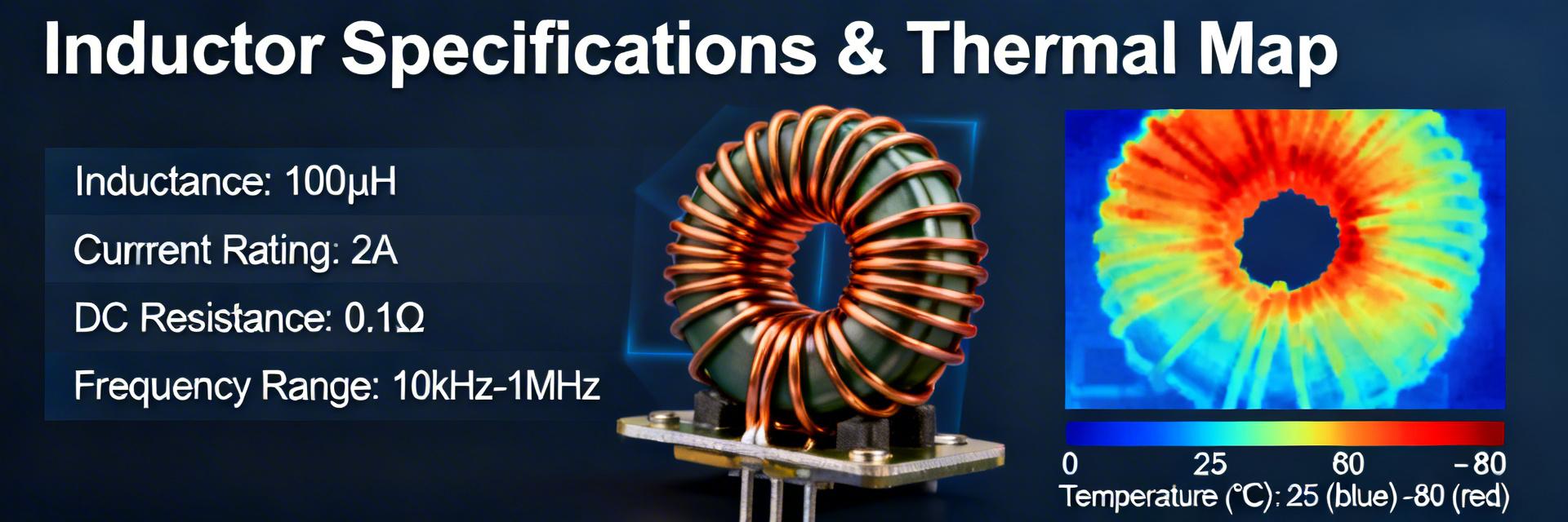
✓ Perform IR thermal imaging on prototypes.
-
✓ Validate DCR at expected board temperatures.
Executive Summary
- Read electrical specs first: DCR, Isat/Irms, and SRF determine in-circuit behavior and efficiency. Always verify measurement conditions before sizing parts.
- Derate for reliability: Target 20–30% headroom for peak current and account for DCR-driven I²R losses in thermal budgets.
- Lab Validation: Measure four-wire DCR, L vs I curves, and impedance at switching frequencies to confirm performance before production release.
Frequently Asked Questions
How should engineers interpret datasheet DCR vs temperature entries?
DCR typically rises with temperature and is often listed at 20°C. Use measured temperature coefficients to adjust DCR in thermal simulations, and perform a four-wire DCR measurement at expected operating temperatures to estimate real losses accurately.
What test steps prove Isat is sufficient for my switching waveform?
Combine L vs I sweep testing with load-step transients using an oscilloscope to capture peak currents. Ensure the inductance remains within the chosen design margin during worst-case peak bias conditions.
Which measurements give the best estimate of in-application temperature rise?
Steady-state thermal imaging under representative load is the most practical method. Correlate IR hotspots with DCR-based loss estimates to validate thermal impedance and long-term reliability margins.