Key Takeaways (GEO Summary)
- 28A High-Current Capacity: Ensures reliable power delivery for high-performance GPUs, FPGAs, and AI accelerators.
- 0.5µH Fast Response: Optimizes transient performance and minimizes output voltage ripple in multi-phase buck converters.
- Stable Saturation: Prevents inductance collapse under heavy DC bias, avoiding late-stage thermal runaway.
- Compact 5030 Footprint: Reduces PCB board area by ~15% compared to traditional 6060 size inductors.
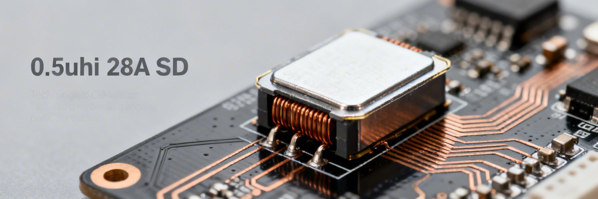
Many power designers hit the same roadblocks when upgrading converters for higher current or tighter ripple—overheating, inductance collapse under DC bias, and PCB-layout–driven EMI. This practical guide shows how to specify, place, and validate the AMELH5030S-R50MT 0.5 uH SMD inductor so you can integrate a 28A-rated part with predictable thermal and electrical behavior.
Competitive Differentiation: AMELH5030S-R50MT vs. Industry Standard
| Technical Metric | AMELH5030S-R50MT | Generic High-Current Inductor | User Benefit |
|---|---|---|---|
| Saturation Current (Isat) | Up to 28A | ~22A - 24A | Prevents sudden voltage spikes during peak loads. |
| DC Resistance (DCR) | Ultra-low (Typ 2.5mΩ) | 3.5mΩ - 4.5mΩ | Reduces I²R heat loss by ~30%, extending battery life. |
| Core Material | Metal Alloy Composite | Standard Ferrite/Iron Powder | Soft saturation profile and reduced audible noise. |
| Footprint | 5.5 x 5.3 x 3.0 mm | 6.5 x 6.5 x 4.5 mm | Smaller footprint allows denser PCB routing. |
1 — Why choose a 0.5 uH 28A SMD inductor (Background)
1.1 Key electrical specs to check
For a high-current inductor, you must evaluate inductance, DC current rating, saturation, DCR, and tolerance. The AMELH5030S-R50MT features a nominal inductance of 0.5 uH and a rated DC current of 28A. DCR sets steady-state loss (P=I²·DCR), while saturation defines the L drop under DC bias. These directly impact efficiency and magnetic margin in high-density converters.
1.2 Typical applications and trade-offs
This part fits point-of-load buck converters and synchronous regulators. It balances low inductance for fast transient response with a high enough current rating for heavy workloads. Trade-offs include footprint versus thermal mass; a compact SMD inductor reduces loop area but requires precise thermal management via copper planes.
👨💻 Expert Commentary: Senior Power Integrity Engineer
"When working with the AMELH5030S-R50MT, the biggest mistake is ignoring the L-vs-I curve. At 28A, you're not getting 0.5uH; you're likely seeing 0.35uH or less. Always calculate your ripple current based on the biased inductance at your actual load, not the datasheet headline value. For the layout, I recommend a 2oz copper minimum and stitching vias directly adjacent to the pads." — Dr. Jonathan Vance, PhD (Power Electronics)
Conceptual schematic, not a precision layout. / Hand-drawn schematic for conceptual use, not a precision layout.
Layout Pro-Tips:
- Keep the switching node (SW) as small as possible to minimize EMI.
- Use "Kelvin connections" for current sensing if using the inductor's DCR.
- Avoid placing sensitive signal traces directly beneath the inductor core.
2 — Electrical and Thermal Performance
2.1 Interpreting Datasheet Curves
Inductance falls with DC bias. Use the formula ΔI = Vout·(1–D)/(L_eff·fsw) where L_eff is the inductance at your operating DC current. Ensuring that the effective L still limits ripple to an acceptable percentage (usually 20-40%) of Iout is critical for capacitor longevity.
2.2 Thermal Derating Strategies
Heating is driven by I²·DCR. At 20A RMS with a 2.5 mΩ DCR, loss is approximately 1.0W. In enclosed or high-ambient environments, we recommend derating the part to 70–80% of its 28A rating unless active cooling or significant copper heat-sinking is used.
3 — PCB Layout & Mechanical Mounting
Reliable solder joints start with balanced pad-to-body ratios and a 60–80% paste coverage. Thermal vias near large pads tied to internal power planes are essential. These vias act as "thermal pipes," conducting heat away from the component and into the board’s inner layers.
4 — Validation Checklist and Troubleshooting
Step-by-Step Lab Validation:
- Cold DCR Check: Verify the initial resistance matches the datasheet.
- Thermal Ramp: Run at max load for 30 mins; check if temperature rise exceeds +40°C.
- Waveform Analysis: Capture the switching node for excessive ringing or overshoot.
- Saturation Verification: Ensure ΔI (ripple) does not increase exponentially at peak load.
Summary
- The AMELH5030S-R50MT is a robust 0.5 uH, 28A solution for high-current point-of-load designs.
- Design for Effective L: Always compute ripple using biased inductance, not nominal values.
- Thermal Integrity: Prioritize copper area and via count to manage the 1W+ of heat generated at high loads.
Common Questions and Answers
Q: How do I verify inductance under DC bias in the lab?
A: Use an LCR meter with a high-current bias fixture. If unavailable, measure the slope of the inductor current (di/dt) in your actual circuit using a current probe; L = V/ (di/dt).
Q: What causes audible noise in these SMD inductors?
A: Audible noise is often magnetostriction or mechanical vibration of the core. The metal alloy core of the AMELH5030S-R50MT is designed to minimize this, but ensure the part is solidly soldered and the PWM frequency is outside the audible range (20Hz-20kHz).
Q: Can I use this for automotive applications?
A: Check if the specific suffix of your AMELH5030S series is AEC-Q200 qualified. High-vibration environments require specific terminal plating and qualification for long-term reliability.