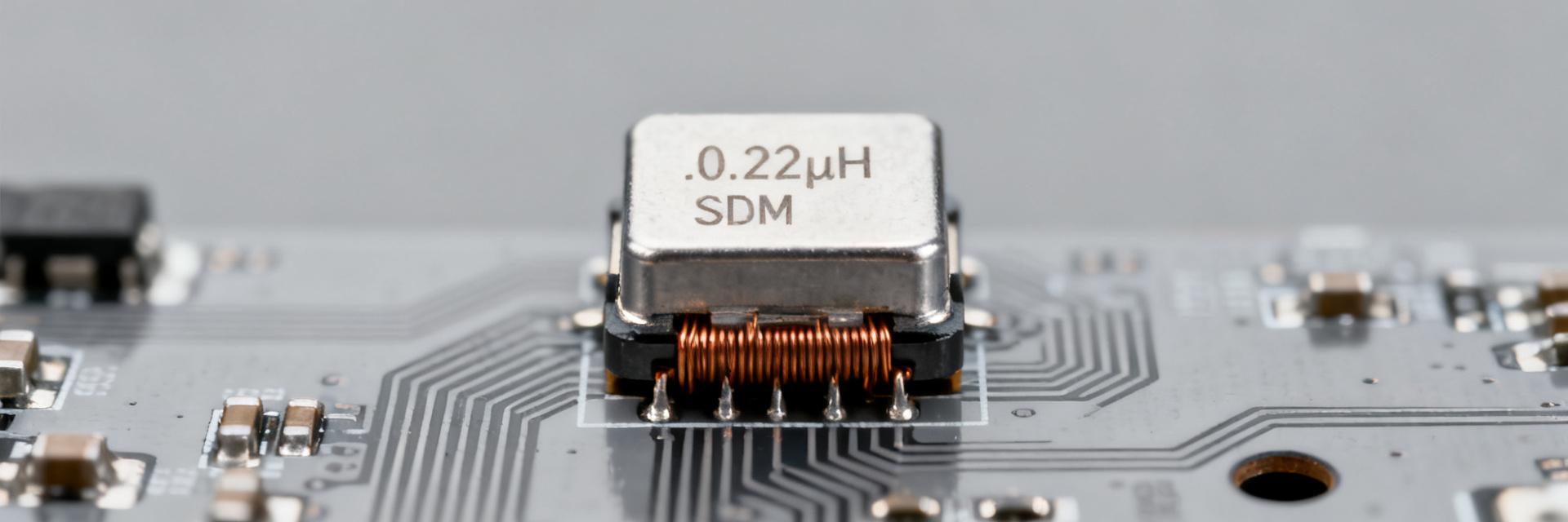
High-current SMD power inductors used in modern DC–DC converters commonly show DC resistance (DCR) in the low milliohm range and saturation currents (Isat) in the tens of amps. The HCM1A0503V3-R22-R combines a 0.22 µH nominal inductance with a max DCR of 2.3 mΩ and an Isat of 23 A. This evaluation provides power designers with the context needed to move from datasheet numbers to reliable PCB implementation.
(1) Product Overview & Technical Specifications
Specs at a Glance
| Parameter | Value (typical / max) |
|---|---|
| Inductance | 0.22 µH (220 nH), ±20% |
| Rated Current (Irms) | ≈15.8 A |
| Saturation Current (Isat) | ≈23 A (@ specified drop) |
| DCR (DC Resistance) | ≈2.3 mΩ (Max) |
| Construction | Shielded SMD, Low Profile |
(2) Performance Analysis: DCR & Isat
DCR and Efficiency Losses
DCR is the primary driver of I²R conduction losses. For the HCM1A0503V3-R22-R, at a continuous current of 15.8 A: P_loss = (15.8²) × 0.0023 ≈ 0.57 W. This dissipation must be managed through PCB copper pours to prevent thermal runaway. Designers should always validate batch-specific DCR using Kelvin sensing.
Isat: Managing Saturation
Saturation current defines where inductance drops (typically 30%). With an Isat of 23 A, this part offers high headroom for ripple. However, operating near Isat increases ripple current and can destabilize the control loop. A 20-40% safety margin is recommended for robust designs.
(3) Thermal Behavior & Layout Strategy
Temperature rise is determined by P_loss and the PCB's thermal resistance (θ). To ensure reliability:
- Compute P_loss and predict ΔT based on available copper area.
- Utilize thermal vias under or near pads to sink heat into internal ground planes.
- Follow the manufacturer's reflow profile to avoid internal stress on the shielded core.
(4) Selection & Implementation Checklist
How should DCR measurement be performed?
Use a four-wire (Kelvin) method to eliminate lead and contact resistance. Apply a low test current per instrument recommendations for the DCR measurement, then validate with a higher current pulse to confirm behavior under load; record ambient and board temperatures to interpret results correctly.
What is the recommended Isat margin for converter designs?
A conservative margin is 20–40% above expected peak current depending on ripple and transient severity. Use the inductance-vs-current curve to quantify how much L falls at your operating bias and ensure converter ripple and loop stability remain acceptable under that reduced L.
Which PCB layout steps reduce thermal and EMI issues?
Short high-current loops, large copper pours, thermal vias under pads, and correct component orientation for shielding are primary actions. Keep noisy switching nodes away from sensitive analog traces and follow the manufacturer land pattern and reflow recommendations.
What are the key specs for HCM1A0503V3-R22-R?
This inductor features a 0.22 µH inductance, a maximum DCR of 2.3 mΩ, an Isat of 23 A, and an Irms of 15.8 A, making it ideal for high-density buck converters.
Summary
The HCM1A0503V3-R22-R is a high-performance solution for high-current rails. Success depends on balancing its low DCR against the thermal limits of the PCB layout and ensuring the 23 A Isat provides sufficient margin for transient loads.