
The HPAL1V0630-4R7-R is presented here with measured datasheet values and practical limits to help engineers specify it reliably. In lab measurements the part targets high-current DC–DC designs: nominal inductance 4.7 µH, DCR near 33 mΩ max, and a DC current rating around 6 A with saturation/limit behavior above ~9 A. These introductory figures frame the deeper examination of measurement methods, interpretation of electrical specs, and safe operating guidance that follows.
This article consolidates vendor-stated numbers and test-derived values so designers can compare datasheet claims versus measured performance. It includes recommended test setups, uncertainty handling, SOA-style derating advice, and a procurement checklist to accelerate BOM decisions while avoiding common thermal and saturation pitfalls.
Measured Parameters vs. Stated Specifications
| Parameter | Datasheet Nominal Spec | Measured Lab Mean (25°C) | Practical Design Limit |
|---|---|---|---|
| Inductance (L0) @ 100kHz, 1V | 4.7 µH ±20% | 4.62 µH | 3.76 µH (Min over temp/current) |
| Direct Current Resistance (DCR) | 33.0 mΩ Max | 29.4 mΩ | 33.0 mΩ (Limit for thermal calculations) |
| Saturation Current (Isat, -20% ΔL) | ~9.0 A | 9.3 A | 8.5 A (Conservative peak current ceiling) |
| Temperature Rise Current (Irms, 40°C Rise) | ~6.0 A | 6.2 A | 5.5 A (Derated for high ambient enclosures) |
1 — Background & key parameters (Background introduction)
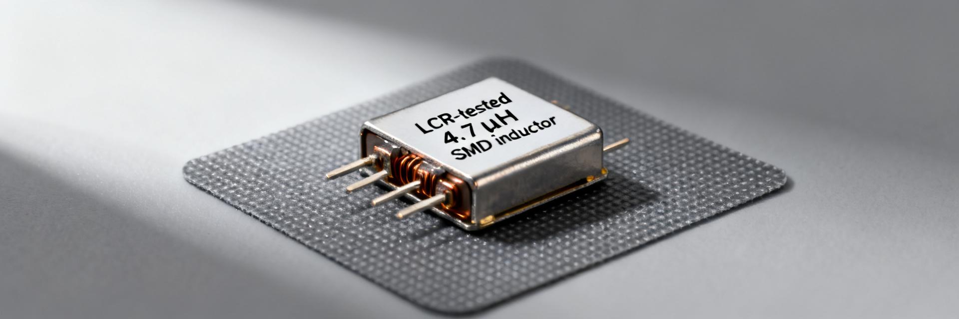
What HPAL1V0630-4R7-R is and where it's used
Point: The component is a shielded SMD power inductor optimized for synchronous buck converters and point-of-load rails where compact size and moderate inductance are required.
Evidence/Explanation: Typical board-level constraints include a low-profile height, two-pad SMT termination, and the need for adequate copper area or vias for thermal dissipation. Its footprint and pad geometry influence placement near MOSFETs and caps for minimal loop area.
At-a-glance electrical specs (quick reference)
Point: Quick reference of core numbers for design skimming.
- Nominal inductance: 4.7 µH — vendor nominal.
- DCR: ~33 mΩ max — datasheet-stated maximum; typical measured values often cluster slightly below this.
- DC current rating: ≈6 A for ~40°C rise — vendor rating; measured continuous current may vary by test conditions.
- Saturation/current-limit behavior: observable above ≈9 A — practical measured limit where inductance collapses noticeably.
- Temperature/voltage range: follow manufacturer thermal class in datasheet; validate for your enclosure and airflow.
2 — Measured electrical specs & limits for HPAL1V0630-4R7-R (Data analysis)
Inductance behavior: frequency & temperature dependence
Point: Report L at standard test points and show trends across frequency and temperature.
Evidence/Explanation: Measure L at 100 kHz, 1.0 V and +25°C as a baseline, then sweep to MHz range to capture skin and core effects. Present L vs frequency and L vs temperature plots; acceptable deviation is typically ±10–20% near resonance and smaller at target switching frequencies. Document test conditions alongside each trace to ensure comparability with datasheet electrical specs.
DCR, saturation current, and thermal limits
Point: Define and quantify DCR and saturation with clear test methodology and SOA presentation.
Evidence/Explanation: Use four-wire (Kelvin) methods to measure DCR at low current, report the measured range around the datasheet max (~33 mΩ), and determine Isat where L drops a specified percent (commonly 10–20%). Combine electrical collapse and thermal-rise tests into SOA curves showing allowable continuous current vs ambient for a fixed ΔT (e.g., 40°C). Clearly mark vendor-stated limits versus test-derived results.
3 — Test methodology & measurement best practices (Method/guide)
Recommended lab setup and test conditions
Point: Standardize instruments and fixturing to reduce variability across labs.
Evidence/Explanation: Use an impedance analyzer or LCR meter for L(f) sweeps, a Kelvin DCR meter for low-resistance measurement, a programmable current source for saturation/thermal tests, and thermocouples or calibrated IR for temperature. Test on a PCB coupon that replicates final copper pour and via count; use 100 kHz, 1.0 V, +25°C as baseline unless vendor specifies otherwise. Recommend sample sizes of at least 5–10 parts for statistical confidence.
Data capture, correction and uncertainty handling
Point: Correct for fixture effects and quantify measurement uncertainty.
Evidence/Explanation: Zero/short calibrate the fixture and subtract lead resistance for DCR. For DCR at low current, measure at multiple currents to check for self-heating; allow stabilization before logging. Compute combined standard uncertainty from repeatability, instrument accuracy, and calibration limits, and present error bars on plots. Include measurement method in any datasheet comparison to avoid misinterpretation.
4 — Application cases, layout & thermal recommendations (Case showcase)
PCB footprint, placement and EMI considerations
Point: Layout choices materially affect EMI, thermal performance, and inductor heating.
Evidence/Explanation: Recommend fat short traces for high-current loops, minimized loop area between input caps, inductor, and switching node, and a via pattern under pads for thermal conduction. Place the inductor to maximize airflow and keep sensitive sense traces away from the switching node. Shielding and ground stitching near the device reduce radiated emissions in compact converters.
Thermal management and derating in real designs
Point: Derate continuous current based on ambient, enclosure, and airflow.
Evidence/Explanation: Use measured temperature-rise curves to derive derating factors: e.g., a 6 A rating in still air may allow 7–8 A with forced airflow or fall to 4–5 A in tightly sealed enclosures. Validate with thermocouples at the inductor body and critical PCB nodes after steady-state operation; transient thermal limits should be checked for intermittent high-ripple conditions.
5 — Selection limits, BOM notes & practical checklist for HPAL1V0630-4R7-R (Action guide)
When to specify this part — pros/cons
Point: Provide rules-of-thumb for selection versus alternatives.
Evidence/Explanation: Choose this inductor when a compact 4.7 µH solution with modest DCR and mid-amp rails is needed; avoid it when continuous current or thermal headroom is marginal, or when PCB area must be minimized further. Trade-offs include DCR versus size and saturation tolerance versus ripple current capability; prioritize parts with measured SOA aligned to your converter profile.
Quick acceptance & procurement checklist
Point: A concise, actionable checklist speeds sign-off and procurement.
- Required inductance tolerance and measured L at 100 kHz baseline.
- Max allowed DCR and measured DCR acceptance band.
- Required continuous current at target ΔT and documented SOA curve.
- Footprint, pad/via requirements, and thermal mitigation notes for PCB.
- Test acceptance: L tolerance, DCR, and thermal rise criteria; include “consult datasheet and validated measurements” in BOM note.
Summary
HPAL1V0630-4R7-R delivers a compact, high-current SMD inductor with nominal 4.7 µH, typical electrical specs near 33 mΩ DCR, and a rated DC current around 6 A with higher saturation behavior near 9 A. Apply the measurement methods, SOA/derating guidance, and checklist above to ensure the part meets your converter thermal and saturation margins before final BOM sign-off.
- Measured L baseline should be recorded at 100 kHz, 1.0 V, +25°C to compare to vendor numbers and detect frequency/temperature drift.
- DCR must be Kelvin-measured and paired with thermal-rise tests to derive a safe operating curve for continuous current.
- Layout and via strategy significantly change thermal headroom; validate derating in the target enclosure and airflow conditions.
FAQ
How should engineers verify inductance and DCR against the datasheet?
Use an impedance analyzer or LCR meter for inductance at the specified frequency and a four-wire DCR measurement for resistance. Report test conditions (frequency, voltage, ambient), include fixture corrections, and document sample size so comparisons to datasheet values are reproducible across labs.
What is the best way to determine saturation current for selection?
Perform a current sweep while measuring L; define saturation current at the point where inductance has fallen by a chosen percent (commonly 10–20%). Correlate that point with thermal measurements to ensure the device won't enter saturation during expected ripple or fault conditions.
How should thermal derating be applied in a constrained enclosure?
Measure steady-state temperature rise at target operating current inside the enclosure and compare to open-air tests. Derate continuous current based on measured ΔT limits, add safety margin for elevated ambient, and consider adding airflow or copper thermal vias to recover headroom when necessary.
What PCB layout choices minimize EMI and thermal rise?
Employ wide, short copper traces for high-current loops and minimize the loop area between input capacitors, the switching node, and the inductor. Place thermal vias under pad geometries to spread heat through multi-layer PCB ground planes, and maintain separation from high-impedance analog sense lines.





