
AMELH6030S-R47MT Inductor: Electrical Limits & Specs
Manufacturer datasheet figures indicate this flat‑wire power inductor delivers low DCR (single‑digit milliohms), saturation behavior in the tens of amps, and an Irms rating specified against a ≈40°C temperature rise — electrical limits engineers must verify for robust power designs. This guide will unpack those electrical limits, show how to test them in the lab, and provide practical selection and PCB layout guidance to ensure the part meets system targets without surprise heating or saturation.
Readers will find a quick spec template, clear definitions for Isat, DCR and Irms, step‑by‑step measurement setups, worked examples for a 10 A buck converter, and an actionable selection and layout checklist aimed at US power‑supply engineers.
1 — AMELH6030S-R47MT: Overview & Quick Spec At-a-Glance
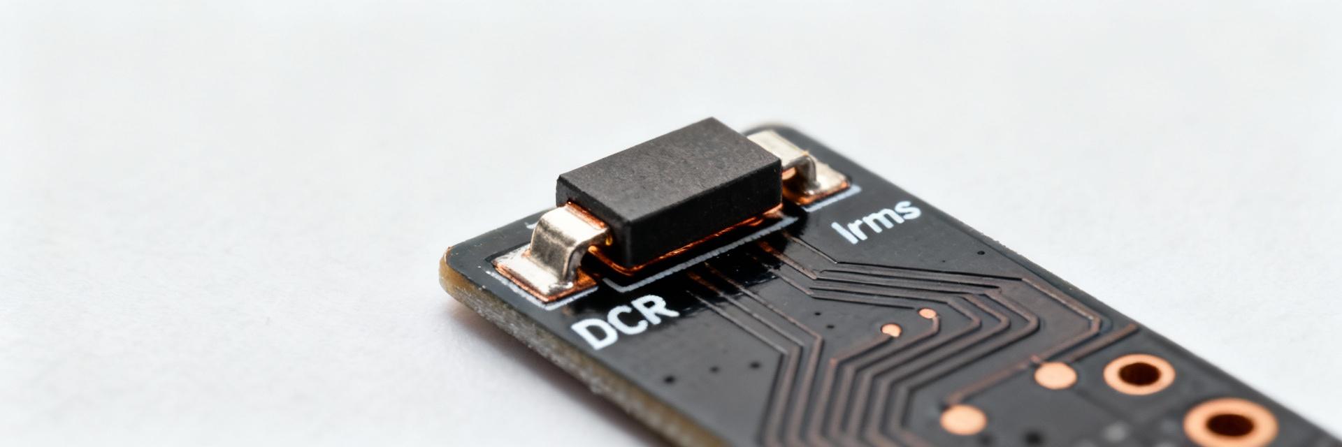
Part characteristics and mechanical/thermal context
The part is a 6030 package flat‑wire, hot‑pressed molded power inductor intended for surface mount PCB use; its flat‑wire topology lowers DCR and spreads copper to improve thermal conduction to the pads. Mounting is SMD with short thermal path through end terminals and PCB copper; thermal impedance depends strongly on pad area, via count, and nearby copper pours. These mechanical traits control how much heat the inductor sheds and therefore directly affect allowable Irms and derating.
Compact spec summary to include in the article
For quick decision making, extract these datasheet fields: nominal inductance (0.47 µH, tolerance), typical DCR (single‑digit mΩ), maximum DCR, Isat definition and test current, Irms referenced to ΔT (often 40°C), operating temperature range, and maximum DC or AC voltage rating. Units should be µH, mΩ, A and °C so engineers see magnitude at a glance.
2 — Electrical Limits Explained: Saturation, DCR, Irms & Thermal Behavior (AMELH6030S-R47MT)
Saturation current (Isat) and inductance under DC bias
Isat is the DC current at which specified inductance drop occurs (commonly 10–30% depending on datasheet). DC bias reduces effective inductance; read the L vs. I curve on the datasheet and interpolate. Example: 0.47 µH nominal, if the datasheet shows a 30% drop at 30 A, expect residual L ≈0.33 µH at that DC bias. Design margin of 20–30% above peak expected currents is typical for transient headroom.
DC resistance (DCR), Irms rating, and temperature rise linkage
DCR sets I²R losses: P_loss = I_rms² × DCR. For a DCR of 7 mΩ and I_rms = 18 A, P_loss ≈2.27 W. That loss must be dissipated through the part and PCB; estimate temperature rise using a conservative thermal path (for example, 10 °C/W from part to ambient yields ΔT ≈23 °C). Verify the datasheet Irms which is often quoted for ΔT ≈40 °C so you can confirm margin at your PCB conditions.
3 — How to Measure & Validate Electrical Limits (test methods and setup)
Lab procedures to measure DCR, inductance under DC bias, and Isat
Use a calibrated four‑wire milliohm meter for DCR (to avoid lead resistance). Measure inductance with an LCR meter while injecting DC bias from a controlled current source or bias tee; modern LCRs with DC bias capability simplify this. For Isat, ramp DC while monitoring L and note the current where the specified percentage drop occurs. Use a thermocouple or IR probe to record temperature during Irms tests and allow steady state before recording ΔT.
Reproducing thermal/Irms conditions and interpreting derating curves
To reproduce datasheet ΔT tests, mount the inductor on representative PCB copper, use the same ambient temperature and minimal airflow, and include the same thermal mass. If your application has higher ambient or restricted airflow, derive an application derating curve: reduce allowable RMS current per 10 °C ambient rise (for example, reduce rated Irms by 8–12% per 10 °C) based on your measured thermal resistance and required reliability margin.
4 — Use-Case Examples & Tradeoffs (case-driven comparisons)
Example: buck converter for 10 A output — selection walkthrough
For a 10 A synchronous buck: estimate inductor ripple ΔI = Vout/(f_sw × L). With 0.47 µH at 500 kHz, ΔI ≈ VΔ/(500k×0.47µ) — compute ripple and then I_pk = I_out + ΔI/2. Compute I_rms for waveform and derive I²R loss using DCR. Compare peak current to Isat and steady RMS to Irms; target 20–30% headroom on Isat/Irms to avoid saturation and excessive heating over the load cycle.
High-ripple or pulsed-current application: evaluating saturation and heating risks
Pulsed peaks can drive temporary saturation even when average heating is acceptable. Evaluate peak currents versus Isat (short pulses may tolerate brief exceedance if core doesn’t demagnetize permanently) and separately compute thermal impact from average I²R heating. For repeated high‑duty pulses prefer parts with higher Isat or use parallel inductors or alternative topologies to reduce peak stress.
5 — Practical Selection, Layout & Procurement Checklist (actionable guidance)
Quick selection checklist before placing the component
Confirm nominal inductance and tolerance for ripple target; check DCR and its effect on power loss; ensure Isat provides 20–30% peak current headroom; verify Irms at your PCB mounting for ΔT acceptance; confirm operating temperature range and assembly height/footprint fits your board and thermal plan.
PCB layout, thermal mitigation, and safety/derating rules
Use large copper pours tied to the inductor pads, add multiple thermal vias under and around pads, and route return paths to minimize stray resistance. Avoid narrow traces under current paths. As a rule of thumb, derate allowable RMS current 8–12% per 10 °C above the datasheet test ambient and maintain at least 20% margin for long‑term reliability in confined enclosures.
Summary
- AMELH6030S-R47MT key electrical limits — Isat, Irms, and DCR — determine suitability; verify these values against in‑circuit peak and RMS currents before final selection.
- Measure DCR with four‑wire methods and L vs. I with a DC bias fixture; compute I²R losses and use measured thermal resistance to predict ΔT versus the datasheet Irms condition.
- Design with 20–30% Isat/Irms headroom, use copper pours and via stitching for thermal relief, and derate allowable RMS current for higher ambient or restricted airflow.
FAQ
How do I measure AMELH6030S-R47MT DCR accurately?
Use a four‑wire milliohm measurement to eliminate lead resistance, ensure good Kelvin contacts to the part pads, and average multiple readings. Perform the measurement after the part cools to ambient to avoid temperature‑induced resistance changes; note that DCR will increase with temperature and affects steady‑state losses.
How to determine AMELH6030S-R47MT saturation current for my application?
Measure inductance while ramping DC current and record the current where inductance falls by the datasheet‑specified percentage (common criteria: 10–30%). Compare that Isat to your expected peak currents including transients and allow 20–30% margin to prevent in‑circuit saturation under worst‑case conditions.
What is the best way to reproduce the Irms ΔT test for AMELH6030S-R47MT?
Mount the inductor on a PCB with the same copper area and via count as your design, set ambient and airflow to match datasheet conditions, apply the RMS current until thermal steady state, and record ΔT with a thermocouple on the part body. Use this measured thermal resistance to predict Irms at different ambient temperatures and to set derating rules.





