News
Understand customer needs and strive to be first-class in quality, delivery, service and environmental responsibility
AMELH6020S-6R8MT Specs & Test Data: DCR, Isat, SRF
Date:
12 February 2026
Source:
Views:
18
AMELH6020S-6R8MT Specs & Test Data: DCR, Isat, SRF
The AMELH6020S-6R8MT is presented here with a tight, data-led snapshot to frame its relevance in modern power designs: the series spans very low DCR down to about 1.3 mΩ on the smallest inductances and saturation currents into the tens of amps on higher-current SKUs.
Background & Part Overview for AMELH6020S-6R8MT
Package, Intended Applications and Electrical Role
Point: The part is a compact power inductor in a molded high-current package intended for surface mount.
Evidence: The footprint and thermal pad arrangement favor low inductance loss and PCB heat spreading.
Explanation: In synchronous buck and point-of-load filters, the 6.8 μH value pushes DCR higher than sub-μH parts but provides more energy storage, which affects ripple, transient headroom, and thermal rise.
Series Performance Envelope
Point: Series variants balance inductance, DCR, and Isat across a wide range.
Evidence: Typical DCR values in the series range from single-milliohm to tens of milliohms.
Explanation: The 6.8 μH SKU sits with moderate DCR and mid-level Isat, offering a balance between I²R loss and energy storage per volume.
Key Electrical Specifications
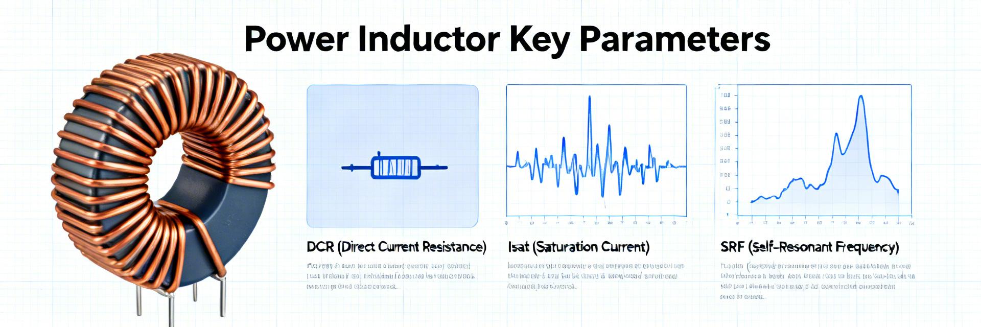
DCR (DC Resistance)
Quantifies I²R loss and thermal dissipation. Lower DCR reduces steady-state losses. Use Kelvin 4-wire technique for measurement accuracy to account for lead parasitics.
Measured vs. Nominal Tolerance
Isat (Saturation Current)
The current where inductance drops (typically 10–30%). Crucial for defining system headroom during transient events and peak loads.
Saturation Knee Curve
SRF (Self-Resonant Freq)
Marks the upper usable frequency limit. Ensure SRF sits well above switching frequencies to avoid unintended resonances.
Frequency Margin
Lab Setup & Test Results
Reliable data requires controlled instrumentation. We recommend using a 4-wire DCR meter, a programmable DC source for Isat sweeps, and an impedance analyzer for SRF.
| Test Category |
Typical Data to Report |
Comparison Target |
| DCR vs. Temp |
Nominal DCR at 25°C, slope per 10–20°C |
Datasheet nominal ± tolerance |
| V–I (Isat knee) |
Inductance drop vs. DC current; knee value |
Datasheet Isat definition |
| SRF Sweep |
Impedance magnitude and SRF peak |
Datasheet SRF where listed |
Design & Layout Best Practices
-
•
Thermal Management: Use wide short traces and via stitching under the thermal pad to reduce PCB thermal resistance.
-
•
Derating Rules: Allow 20–40% headroom for Isat based on worst-case ambient temperatures.
-
•
Filtering: Place SRF well above the switching frequency to avoid LC resonance issues.
Troubleshooting Checklist
!
Verify DCR limits against thermal damage.
!
Check for early saturation under peak transients.
!
Isolate resonances with impedance sweeps.
Summary & Final Evaluation
Comparing datasheet entries to lab measurements highlights that DCR, Isat, and SRF are the practical levers for inductor selection. The AMELH6020S-6R8MT should be evaluated for production readiness by documenting a datasheet-vs-lab table and three key diagnostic plots:
1. DCR Analysis
Kelvin 4-wire reporting vs. DC bias.
2. Isat Validation
Inductance vs. current knee plotting.
3. SRF Mapping
Impedance sweep to avoid harmonics.
Frequently Asked Questions
+ How is DCR measured for consistent results?
Use a calibrated 4-wire (Kelvin) fixture, zero the instrument, average multiple readings, and thermally stabilize the part at target temperature. Record DCR at production board conditions to capture assembly impacts.
+ What is the practical way to detect the Isat knee?
Sweep DC current slowly while measuring inductance or V–I slope; the knee is where inductance drops by the datasheet’s specified percentage. Validate dynamic saturation behavior using waveform captures under transient loads.
+ How should SRF measurements influence layout and filtering?
Measure impedance vs. frequency to find SRF and ensure it sits above switching harmonics. If SRF is near the switching frequency, add damping or adjust filter topology. Layout that minimizes parasitics raises usable SRF and reduces spurious resonances.